Aside from building software I occasionally like to tinker with electronics. It’s a fun hobby that allows me to spend more time away from a screen.
I also appreciate a good night’s sleep. Recently my son started waking up randomly in the middle of the night, under the impression that morning has come. This is all fine, until it becomes a regular occurence, and it starts affecting everyones sleep patterns.
I learned from other parents that a sleep trainer or ‘OK-to-wake clock’ could be the answer. Sleep trainers are simple devices that indicate if it’s still time to sleep or time to wake up: a clock for kids that can’t read clocks yet. There are many commercial options available, and they come in different shapes and forms.
I could’ve bought one for €30 to get this done quickly but where’s the fun in that. So, let’s build one ourselves.
The requirements I have are:
- it should be a night light
- 2 colours to indicate sleep and wake-up time
- easy to configure the schedule
- as little maintenance as possible
- cute design
- no batteries
I have some random electronics left over from previous projects, including an ESP8266 ESP-01S. It’s a small version of the more popular ESP32, with only a few IO pins and no USB-port. It does have WiFi and more importantly: it super cheap and we can easily integrate it with Home Assistant using ESPHome. With ESPHome we can flash some firmware on the device which will run a small web server with APIs so it can be controlled and updated Over The Air using Home Assistant.
Flashing the ESP-01S
Flashing the ESP-01S is probably the trickiest part if it’s your first time doing this. You only need to flash it once; further updates can be done over the air. There are several methods of flashing but before you start, you’ll need to install the ESPHome add-on in your Home Assistant system. Follow this guide to get started.
One (slightly complicated) way to flash your ESP is using a FTDI FT232RL USB Serial Port adapter that you can probably get from China or a local electronics shop. This article describes the process of flashing with the FTDI adapter.
Personally, I use a poorly designed USB to ESP-01 Adapter Board, which works after I modified it to allow me to bridge GPIO-0 and ground to put the ESP into programming mode. This instruction describes the needed modifications.
It seems that there are better adapters available now so if you are just getting started, I suggest checking this forum post by nrutman, which links to an adapter that has the switch to bridge GPIO-0 and ground built-in (this one).
ESPHome device configuration
You can use the following configuration to flash onto the device, which is quite basic since the device only needs to control 2 leds:
esphome:
  name: sleeptrainer
  friendly_name: Sleeptrainer

esp8266:
  board: esp01_1m

# Enable logging
logger:

# Enable Home Assistant API
api:
  encryption:
    # You’ll want to change this key, just create a new device in ESPHome and paste the key from there
    key: "P6ICH8KfyL43iFVXXDKFWlY3oIOZIH+BxUNHd3j0nTU="

ota:
  # change this password, you can also take it from a new ESPHome device
  password: "4d2f4ba29f76ca3ec66ef4ef3cc03353"

# since the WiFi credentials can used in many different devices you can set them centrally in secrets.yaml of ESPHome
wifi:
  ssid: !secret wifi_ssid
  password: !secret wifi_password

light:
  - platform: binary
    name: "Blue light"
    output: blue_light_output

  - platform: binary
    name: "Red light"
    output: red_light_output

output:
  - id: blue_light_output
    platform: gpio
    pin: GPIO2

  - id: red_light_output
    platform: gpio
    pin: GPIO0
The configuration exposes 2 (binary) lights to Home Assistant and binds them to the 2 IO pins (0 and 2) on the device.
Power
Small projects like this can be powered using USB. It’s common to use an old phone-charger as a power source, however the ESP-01S needs an input voltage of 3.3V which is a bit annoying because we can’t power it directly from USB. Fortunately, I still have a 5V to 3.3V Buck Converter. It’s a bit bulky but it should do.
The 5V and ground can be taken from a stripped USB cable.
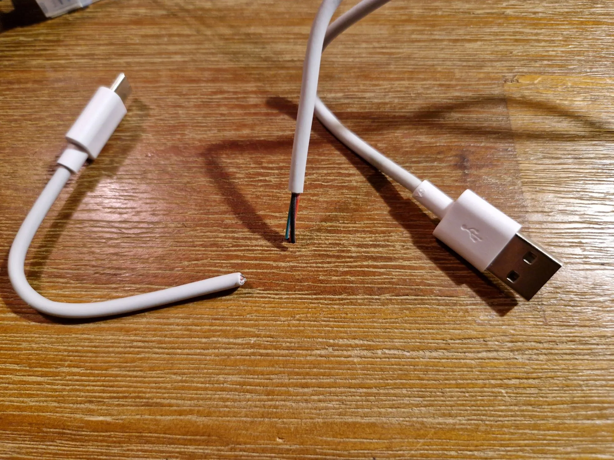
I crimped some Dupont connectors on it so the power cable can be disconnected from the project.
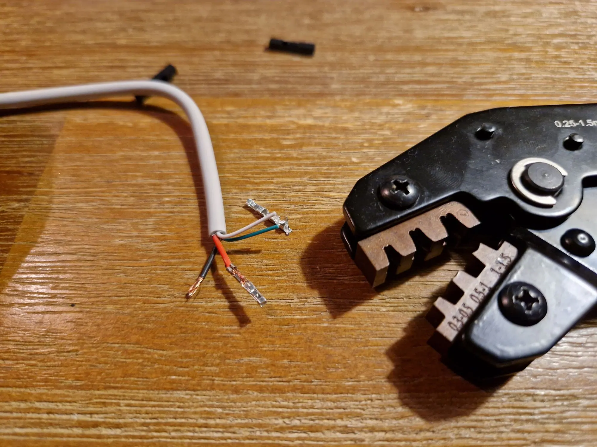
Make sure to measure the wires first using a multi-meter because some of these cables cannot be trusted. My cheap Chinese USB-cable had the 5V and ground wires swapped, with black being 5V and red being the ground.
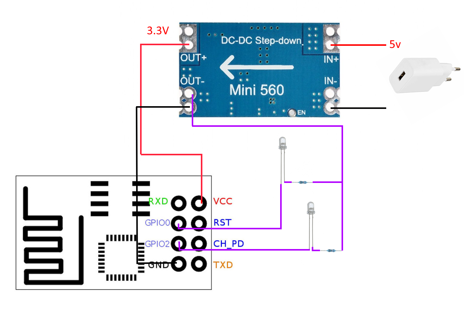
Circuit
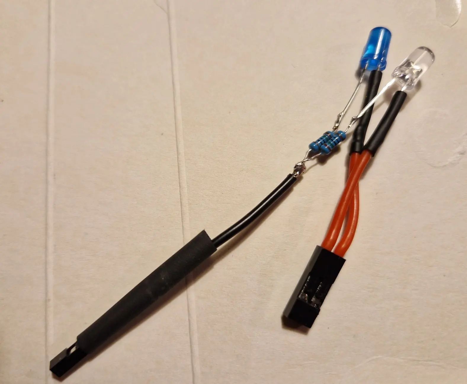
For a quick first version, I wanted to keep the circuit simple (though it could have been much simpler, more on that later). I power the leds directly from the IO-pins on the ESP. The IO pins have a max current of 12mA per pin. The blue and red leds use 3.5 and 8.5 mA so this is well within the limits. These leds are not very bright which is perfect for the use-case because we only need a dim light in the dark bedroom.
I added 2 150Ω resistors in series to the leds to prevent them from burning.
Schematically the circuit looks like this:
Breadboard prototype
It’s always nice to test the circuit before soldering everything together.
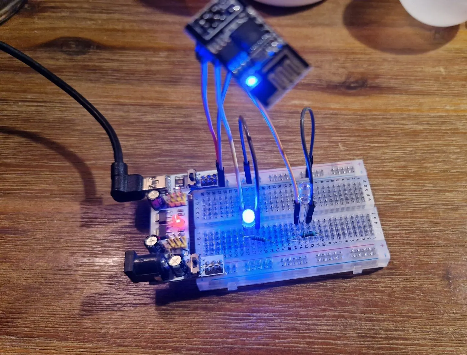
The breadboard power supply (on the left) can be configured to supply 3.3V so the step-down converter is not yet part of the setup.
One thing I found when testing the circuit is that the onboard blue led of the ESP-01S is ON when GPIO2 is LOW. Since we use GPIO2 to toggle one of the leds it will be always on when the leds are off. There is no way to disable this through software so I ‘fixed’ it by sticking some electrical tape on the led. Not very elegant but it works.
Now that everything is tested, we can solder the leds to the resistors and add some Dupont connectors so we can remove it from the project later, if needed.
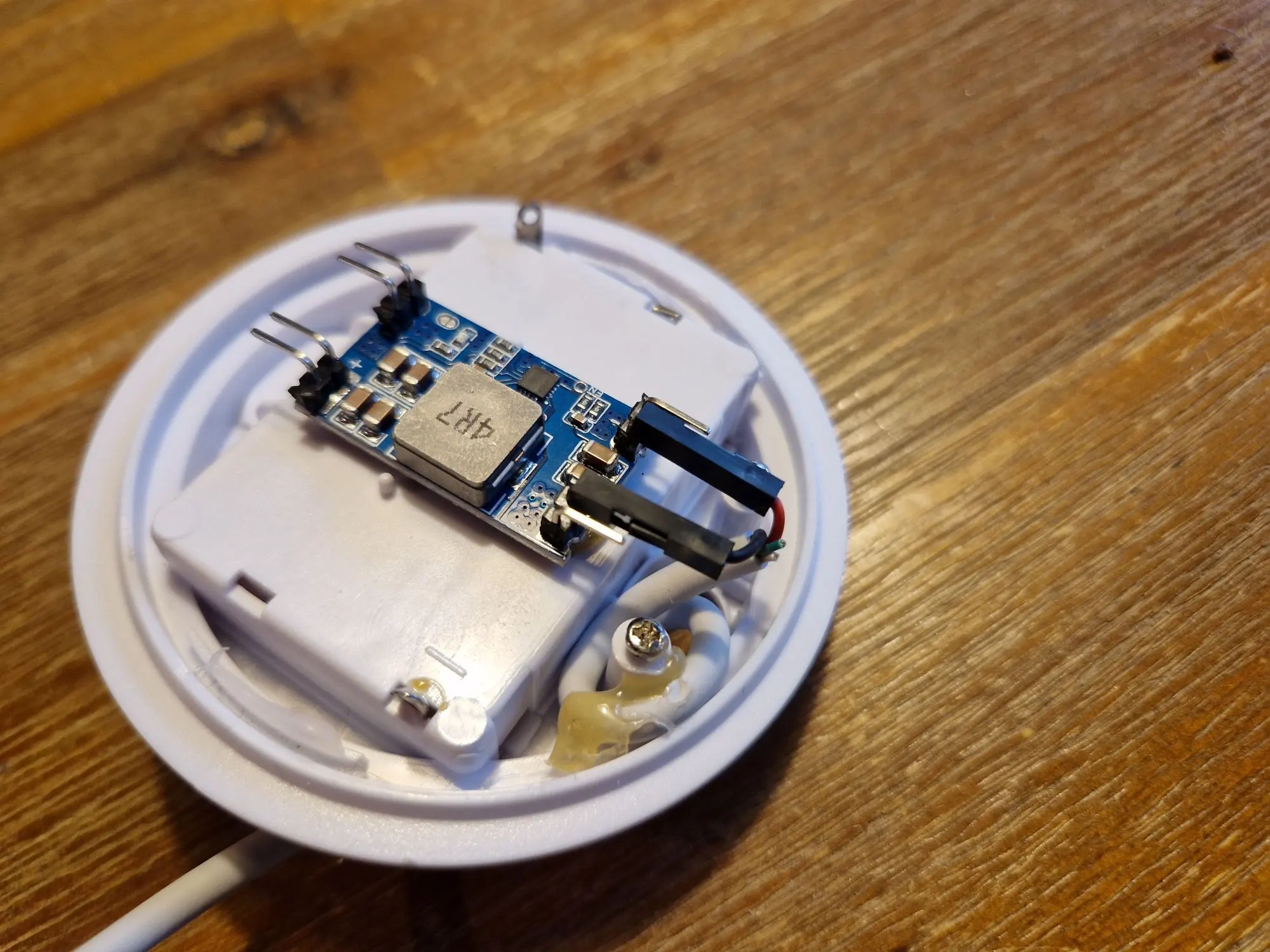
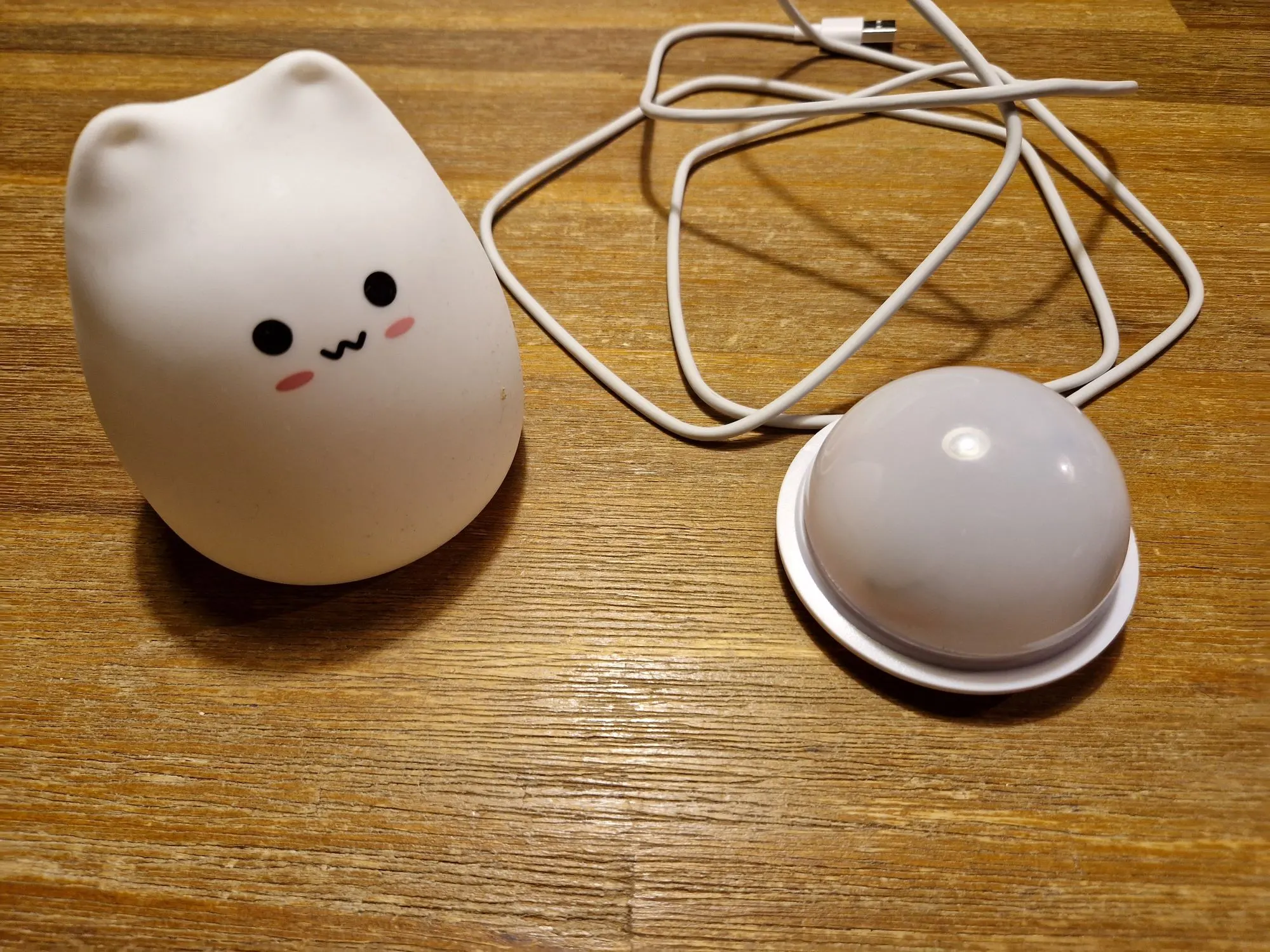
Casing
The appearance of the light is probably the most important part to get right since it needs to pass the ‘child acceptance test’. I have an small old battery-powered cat lamp that should be just big enough to house the project. By stripping out the electronics and feeding the USB cable through the hole of the on-off button there is just enough room for the step-down converter:
Then we can jam in the rest of the components:
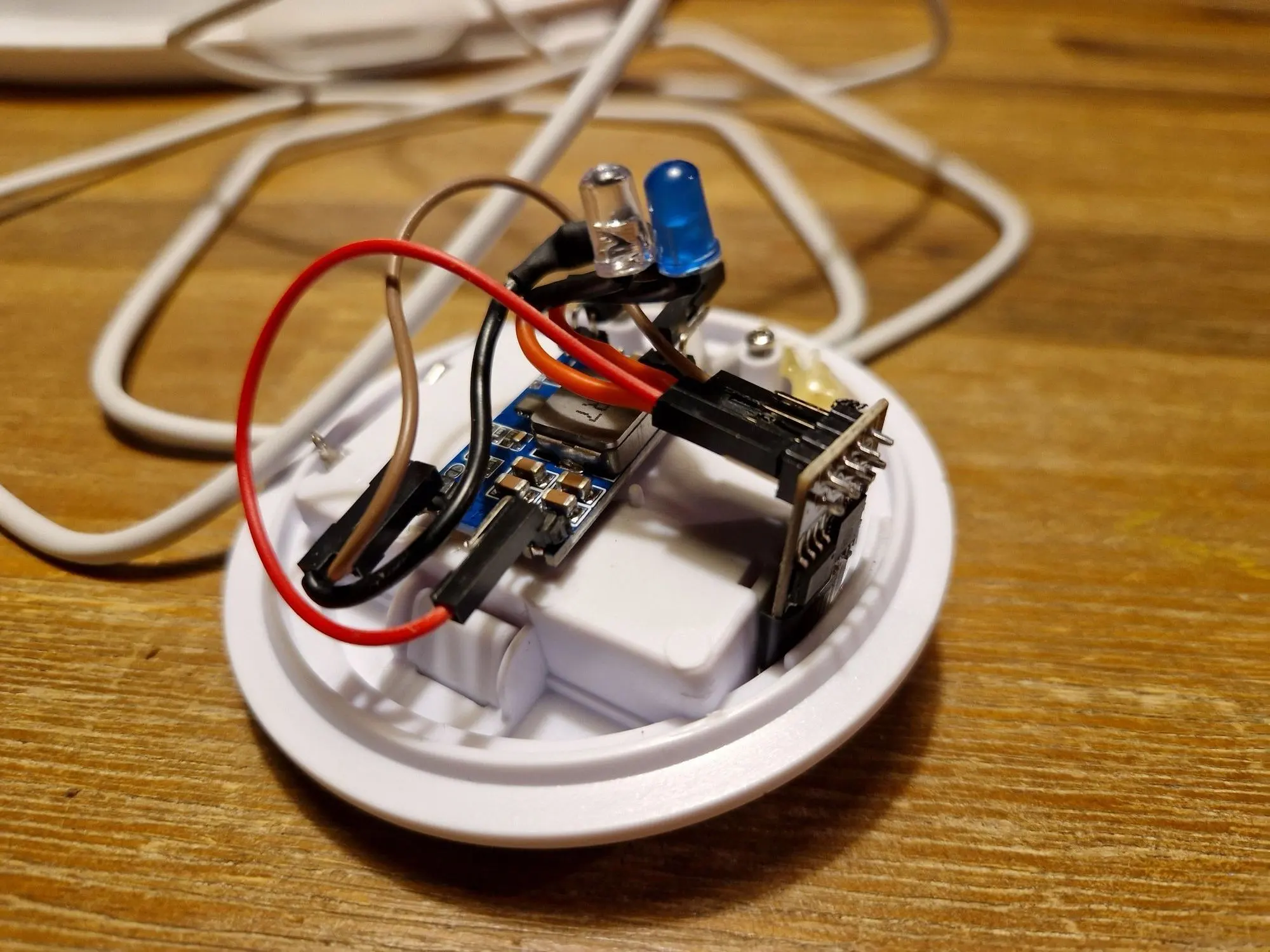
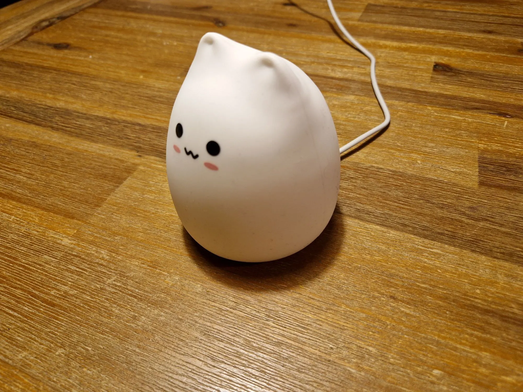
The original lamp has a plastic cap that acts as a diffuser for the leds to create a more evenly distributed light source. It also conveniently hides the messy electronics and wires:
And finally, we place the flexible exterior over the diffuser, and we’re done!
Home Assistant automations
With the hardware sorted out we can configure the software. This is probably the easiest part.
The following automation turns on the red led at bedtime each night:
alias: "Sleeptrainer bedtime"
description: "Turn on red led"
trigger:
  - platform: time
    at: "19:00:00"
condition: []
action:
  - service: light.turn_on
    target:
      entity_id: light.sleeptrainer_red_light
mode: single
The second automation triggers each morning and turns off the red led and toggles the blue led. After 45 minutes the blue led turns off too:
alias: "Sleeptrainer wake up"
description: "Turn off red led, turn on blue led"
trigger:
  - platform: time
    at: "07:00:00"
condition: []
action:
  - service: light.turn_on
    target:
      entity_id: light.sleeptrainer_blue_light
  - service: light.turn_off
    target:
      entity_id: light.sleeptrainer_red_light
  - delay:
      hours: 0
      minutes: 45
      seconds: 0
      milliseconds: 0
  - service: light.turn_off
    target:
      entity_id: light.sleeptrainer_blue_light
mode: single
Improvements
There is an easier way to build ESP-01S controlled lights that require little to no soldering. For this you need a
ESP-01S RGB Led Controller Module with some WS2812(B) RGB led strips or rings. The module has a built-in voltage regulator, so you do not need a step-down converter. These leds are also much brighter than the leds we used in this project and the brightness and colour can be controlled from Home Assistant.
I didn’t own this led controller module when I started the project otherwise I would have probably used it instead.
Conclusion
This was a fun little project that might be a bit over-complicated for the simple features it has. It did prove to be very effective since my son no longer wakes up and stumbles to the master bedroom each night. The integration in Home Assistant ensures that there are no clocks to sync and that the schedule can be tweaked and changed easily.